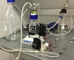
Preparing the System
- Fit the growth chamber into the band on the turbidostat controller, on top of the stir plate.
-
Connect the air pump to the syringe-style filter on the input to the air scrubber.
Air should bubble into the humidifer and may continue to bubble slowly as the system is set up.
- Snake the waste line through a conical tube holder (or similar) in order to create an “S” trap.
-
Uncap the waste line and put the end into a waste reservoir.
The humidifer should bubble more vigorously once the waste line is uncapped. Occasionally, air flow through the humidifer will be blocked by wetting of the filter on the air inlet. If this happens, spray the air inlet connector on the humidifier with 70% ethanol, remove the wetted filter, and replace it with a fresh filter.
- Insert the thin peristaltic pump tubing on the media line into the media pump.
- Flip the cover latch up until you can pull the cover off of the pump
- Remove the tubing restraints from the cover and put one clip on the tubing
- Place the clip with tubing in the cover and thread the tubing around the cover. The pump should turn clockwise. If you’re facing the pump, media will move from the left side to the right side.
- Clip the tubing on the other side of the cover as well
- Slide the cover back onto the pump and flip the cover latch down
- Connect the media line to the media reservoir.
- Spray the media line connector and the media delivery connector on the reservoir with 70% ethanol.
- Uncap the connectors and join them together.
- Prime the media line by running the media pump.
- Use
pto manually activate a pump - Select the pump connected to the media pump line, e.g.
A. - Specify 100 seconds of pumping
-
Watch flow of media through the feed line and stop the pump by hitting any key as soon as media starts to drip into the growth chamber.
If the line was installed backwards in the peristaltic pump, air will bubble into the media reservoir; if this happens, simply reverse the pump tubing and re-prime the line.
# band-dsp-feather manual [acghmpsz] > p # Which pump [A,B,C,D]: a # Enter pump duration (sec): 100 # Planned pumping time: 100 sec (any key to interrupt) # Pumped 76.957 seconds # band-dsp-feather manual [acghmpsz] > - Use
-
Fill the growth chamber with media.
- Use
pto manually activate a pump - Select the pump connected to the media pump line, e.g.
A. -
Specify 800 seconds of pumping
# band-dsp-feather manual [acghmpsz] > p
# Which pump [A,B,C,D]: a
# Enter pump duration (sec): 800
# Planned pumping time: 800 sec (any key to interrupt)
# Pumped 800.000 seconds
# band-dsp-feather manual [acghmpsz] >
Note that pumping time can be used to compute media volume. The peristaltic pump runs at 315 revolutions per minute. With ID 1.0mm tubing, it delivers 48 µl / revolution, or 252 µl / second. At this pumping rate, 800 seconds of pumping delivers 202 ml of media.
- Use
- Switch on the stir plate
- Rotate the growth chamber within the controller band to ensure that the printing on the side of the bottle does not line up either with the LED or the photodetector.
Inoculation
-
Begin turbidity measurements
Use the
mcommand in the controller software. The turbidity measurements should read a small value (typically between 0.1 and 0.5). Leave the measurement running during inoculation.# band-dsp-feather manual [acghmpsz] > m M time.s neph gain M 1972.2 0.526 5 M 1972.7 0.709 5 M 1973.2 0.725 5 M 1973.7 0.735 5 M 1974.2 0.620 5 ... -
Shut off the air input. Clamp the silicone tubing from the air pump to the humidifier, or detach the tubing entirely.
Positive air pressure in the growth chamber will force media out of the inoculation connector when it is uncapped. Remove positive pressure before uncapping the inoculation connector.
- Spray the closed inoculation connector with 70% ethanol
- Uncap the inoculation connector
- Remove a sterile Luer syringe from its wrapping. Pull out the plunger and return it to the wrapping, and attach the syringe barrel to the inoculation connector.
- Transfer the inoculum into the barrel of the syringe using a pipette
- Insert the plunger into the syringe barrel and push it down to deliver the inoculum. Pull the barrel up and down a few times to ensure that all of the inoculum is added to the media.
- Restart the air input by unclamping or reattaching the tubing from the air pump.
- Allow the inoculum to mix homogeneously throughout the growth chamber, which typically takes a minute or so.
- Note the change in turbidity measurement and determine the relationship between cell density and turbidity.
...
M       2034.0   0.422  5
M       2034.5   0.412  5
M       2035.0   0.544  5
M       2035.5   0.613  5
M       2036.0   0.703  5
M       2036.5   0.651  5
M       2037.0   0.501  5
M       2037.5   0.510  5
M       2038.0   0.622  5
M       2038.5   0.623  5
M       2039.0   0.456  5
M       2039.5   3.053  5
M       2040.0   1.644  5
M       2040.5   1.715  5
M       2041.0   6.748  5
M       2041.5  12.634  5
M       2042.0  10.852  5
M       2042.5   9.702  5
M       2043.0   8.681  5
M       2043.5   6.704  5
M       2044.0   6.003  5
M       2044.5   6.259  5
M       2045.0   6.042  5
M       2045.5   5.910  5
M       2046.0   5.975  5
M       2046.5   5.817  5
M       2047.0   5.727  5
M       2047.5   5.336  5
M       2048.0   5.289  5
M       2048.5   4.882  5
M       2049.0   5.545  5
M       2049.5   6.430  5
M       2050.0   6.302  5
M       2050.5   6.421  5
M       2051.0   6.523  5
M       2051.5   6.359  5
...
M       2096.7   6.439  5
M       2097.2   6.167  5
M       2097.7   6.414  5
M       2098.2   6.593  5
M       2098.7   6.312  5
M       2099.2   6.515  5
M       2099.7   6.494  5
M       2100.2   6.892  5
In this example, the turbidity increased from ~0.5 to ~6.5 after inoculation.
Using the cell density of the inoculum and the volume of media, compute the density of cells in the growth chamber. For example, if the above inoculation used 3.0e8 cells into 200 ml media, this would yield 1.5e6 cells / ml.
In this example, a turbidity of 6.0 corresponds to 1.5e6 cells / ml, and 1.0 turbidity unit corresponds to 2.5e5 cells / ml.
Turbidostatic Growth
-
Determine the target culture turbidity.
The cell density to turbidity ratio computed during inoculation may be useful here. For example, if 1 turbidity unit corresponds to 2.5e5 cells / ml, then a target cell density of 2.5e6 cells / ml would correspond to a turbidity measurement of 10.0.
-
Set up the turbidostat controller. Use the
scommand to set up a controller, and then select the Turbidostat controller witht. -
Enter the parameters to configure the turbidostat.
-
The “Target neph” parameter is the target turbidity (nephelometry)
-
The media pump determines which pump will be activated when the turbidity rises above the set point.
# band-dsp-feather manual [acghmpsz] > s # Pick a controller to configure # CONFIGURED CONTROLLER: NONE # CONTROLLERS: # m Manual # t Turbidostat # r Turbidostat Ratio # i Turbidostat Induce # c Turbidostat Cycle Time Conc # g Turbidostat Gradient Time Conc # l Turbidostat Log-Gradient Time Conc # d Turbidostat Density Gradient # Pick a controller: t=Turbidostat # Current settings: # Target neph 40.951 # Pump A # Hit return to leave a parameter unchanged # Enter target neph measurement(40.951): 10 # Enter media pump (A): * # (not updated) # Current settings: # Target neph 10.000 # Pump A -
-
Start the turbidostat controller. Use the
ccommand to start the configured controller. -
The running turbidostat will measure cell density and report data every second.
-
Data lines from the turbidostat controller will begin with
Tso they can be extracted from log files easily. -
The
time.scolumn reports on the time (in seconds) since the controller was started. -
The
nephcolumn reports on the turbidity (nephelometry) measurement -
The
gaincolumn reports on the gain setting for the turbidity measurementNote that the gain factor is not divided out of the
nephdata. For example, anephvalue of 3.0 with againfactor of 2 is equivalent to anephvalue of 7.5 with againfactor of 5. -
The
targetcolumn reports on the target turbidity setting. -
The
pumponcolumn is 1 when the pump was active during the preceding second and 0 when the pump was not active. -
The
pumptime.scolumn reports on the cumulative pumping time, in seconds.
# band-dsp-feather manual [acghmpsz] > c T time.s neph gain target pumpon pumptime.s T 0 6.758 5 10.000 0 15.000 T 0 6.941 5 10.000 0 15.000 T 1 6.958 5 10.000 0 15.000 T 2 7.214 5 10.000 0 15.000 T 3 7.075 5 10.000 0 15.000 T 4 6.962 5 10.000 0 15.000 T 5 7.109 5 10.000 0 15.000 -