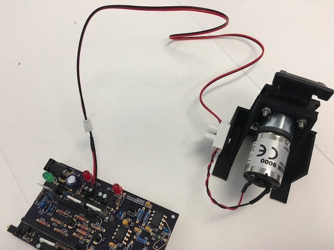
Peristaltic Pump
Ordering information
- Peristaltic pump:
-
Boxer 9K 12VDC 315 rpm 3 roller, Boxer 9022.000
We have used exclusively this pump in our work.
-
Boxer 9QQ 12VDC 315 rpm 3 roller, Boxer 9022.930
This pump is recommended as a replacement for the 9K in new designs. The tubing and mounting appear compatible with the 9K. The pumping rate is slightly faster: 55 µl per revolution as opposed to 48 µl per revolution with the Boxer 9K, and the same angular speed.
-
-
The motor is mounted on a 3D printed piece in the
motor-mount.stlfile located indesign/housing. -
Two-circuit screw-connector barrier strip: Molex Eurostyle 39100-1902, Digi-Key WM12408-ND
- 50 cm JST-PH extension cable, Adafruit 1131
Equipment
-
Diagonal cutters
-
Wire strippers
-
Small phillips screwdriver
-
Heat gun
Consumables
-
Hookup wire (red and black)
-
M3 x 12mm pan head phillips screw, 316 stainless: McMaster-Carr 90116A157
-
M3 hex nut, 316 stainless: McMaster-Carr 94150A325
Mounting the pump requires four M3 screws and nuts
-
M2 x 12mm pan head phillips screw, 316 stainless: McMaster-Carr 90116A022
-
M2 hex nut, 316 stainless: McMaster-Carr 94150A305
Mounting the barrier strip requires one M2 screw and nut
Assembly
The peristaltic pump is mounted on a 3-D printed housing and wired to a barrier strip on the same housing, which is connected to a 2-conductor JST cable.
-
Flip the cover latch up until you can pull the cover off of the pump
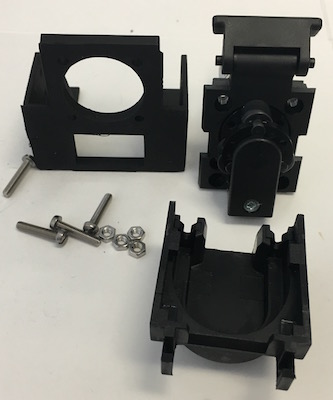
- Insert the pump motor body into the large hole on the pump stand
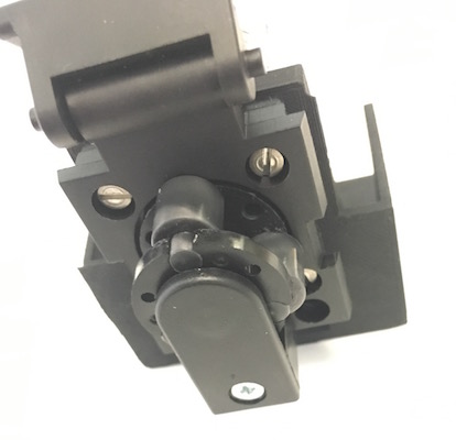
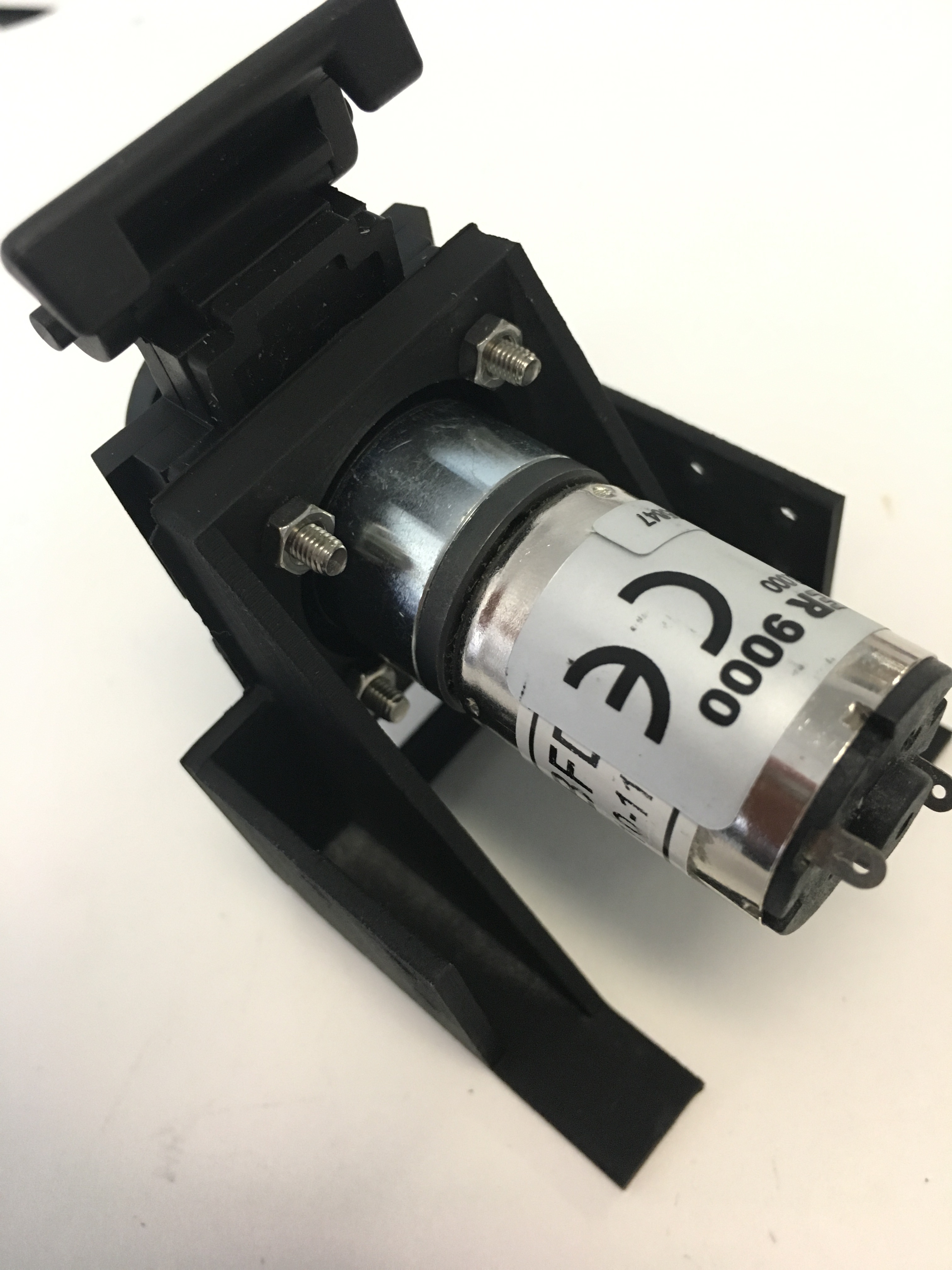
- Align the mounting holes on the pump face with the mounting holes on the stand.
- Insert M3 x 12mm screws into the holes
-
Thread M3 hex nuts onto the other ends of the screws and tighten
-
Align the hole in the center of the barrier strip with a hole on the side of the pump stand.
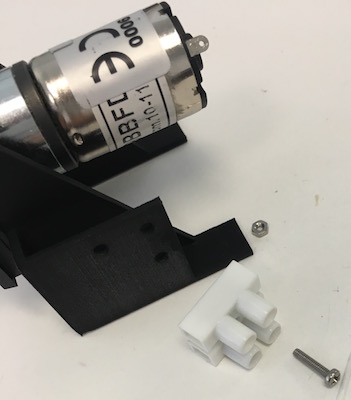
-
Thread an M2 screw through the aligned holes. Attach an M2 hex nut on the other end and tighten.
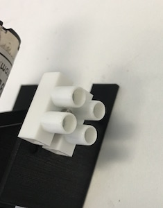
-
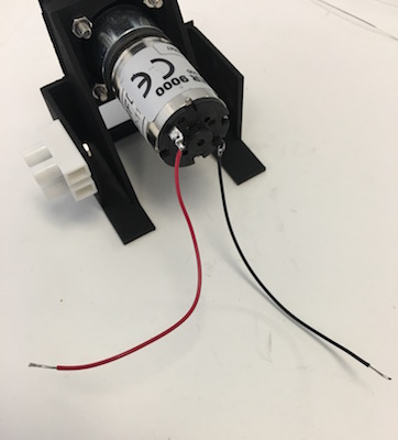
Cut matched 5cm pieces of red and black hookup wire. Strip a short length on each end.
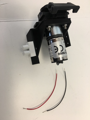
-
Thread one end of the red wire through the solder tab marked with a small
+, twist it around, and solder it.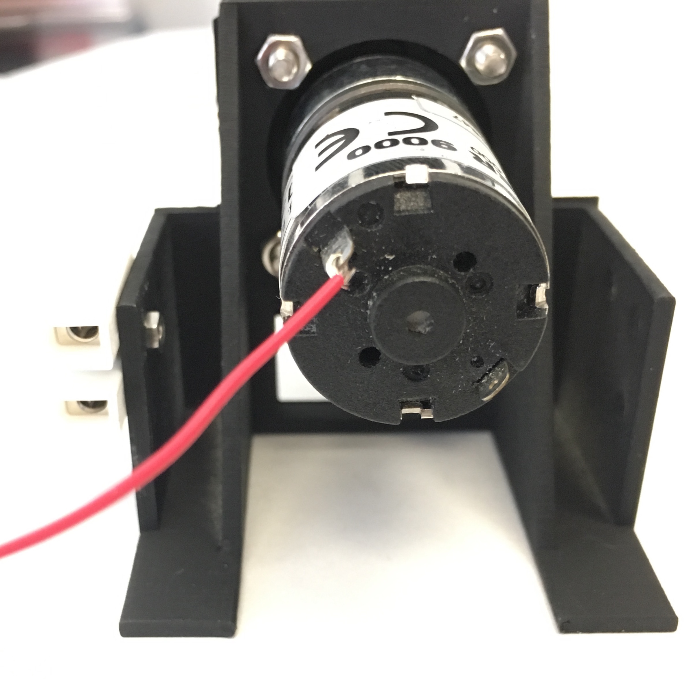
-
Solder the black wire onto the other solder tab in the same way.
-
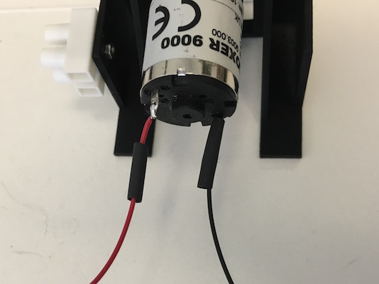
Cut two short (~1 cm) pieces of heat shrink tubing and thread them over the wires until they cover the solder tabs on the motor.
-
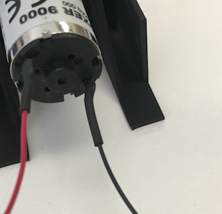
Shrink the tubing with a heat gun
-
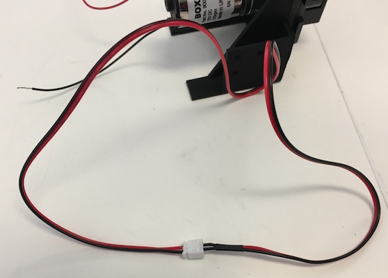
Cut a JST PH 2-wire extension cable ~2 cm from the female end
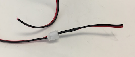
-
Strip the wires on both ends of the cut cable and tin the ends
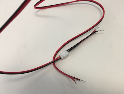
The short cable with the female connector is connected to a screw terminal on the printed circuit board.
-
Screw the red and black motor wires into one side of the barrier strip. Screw the red and black wires of the longer JST cable with a male connector into the other side of the barrier strip, matching the red wires together across the strip.
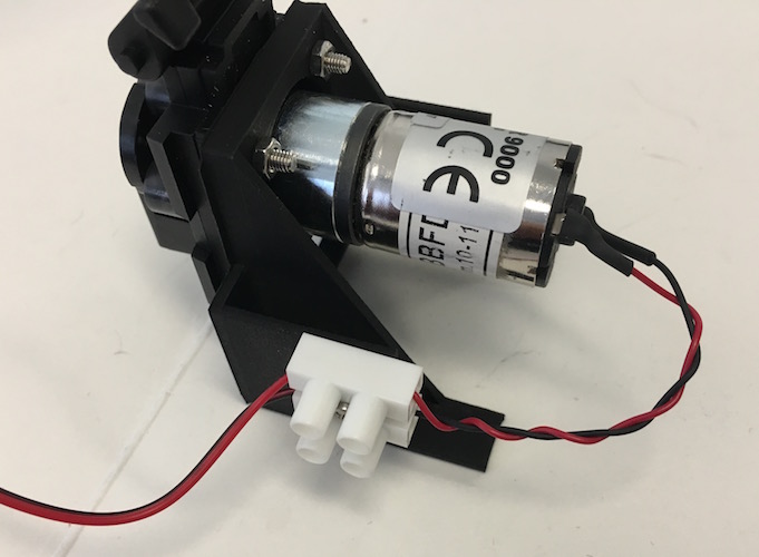
-
The JST cable on the motor can plug in to the JST cable on the circuit board
