Controller Housing
Ordering information
The housing is assembled from two separate pieces that are produced by 3D printing, painted black, and then screwed together. Files for 3D printing are located in design/housing.
-
The
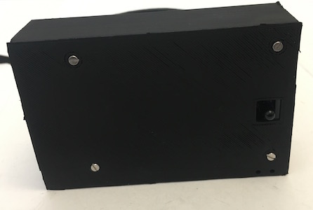
feather-nephel-housing.stlfile prints an enclosed box for the printed circuit board with a square hole for the photodetector. On filament deposition printers, put the widest face of the box on the build plate, with the other walls extending vertically. -
The
250-ml-band.stlfile prints a band that wraps around a 250 ml bottle, with holes for the photodetector and the LED. The500-ml-band.stlfile prints a band that fits a 500 ml bottle instead. On filament deposition printers, put the band upside-down, with the flat top on the build plate and the legs extending upward.
These files can be printed in PLA plastic on widely available 3D printers (we use an Ultimaker 2+) or fabricated by 3D printing services.
Equipment
- Small phillips screwdriver
Consumables
-
Krylon Ultra-flat Black 1602 spray paint
This ultra-flat black spray-paint is highly absorbing in the near-infrared wavelength used to measure turbidity. Many other visually black materials reflect near-IR light.
-
M2 x 8mm pan head phillips screw, 316 stainless: McMaster-Carr 90116A015
-
M2 hex nut, 316 stainless: McMaster-Carr 94150A305
Assembling the housing and mounting the PCB requires eight screws and nuts.
Assembly
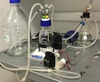
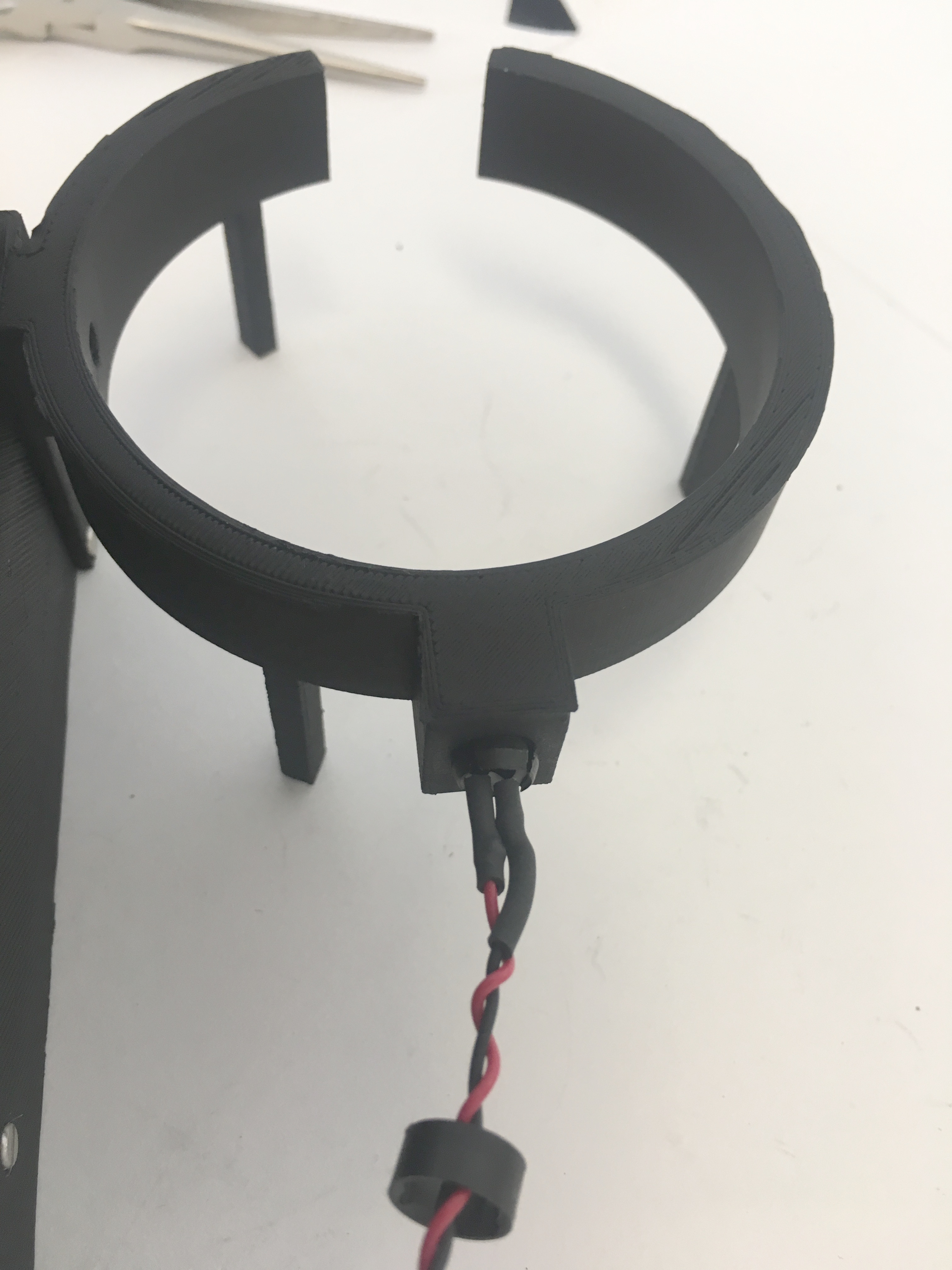
The controller housing is printed as two separate components, a “band” that wraps around the growth chamber and a “box” that houses the detector circuit board.
-
Remove any support material from the printed parts.
-
Spray paint the band and the box flat black, paying particular attention to the holes for the LED and the photodiode. Allow to dry overnight.
-
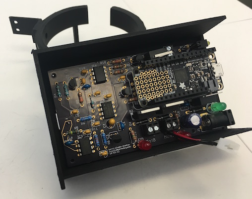
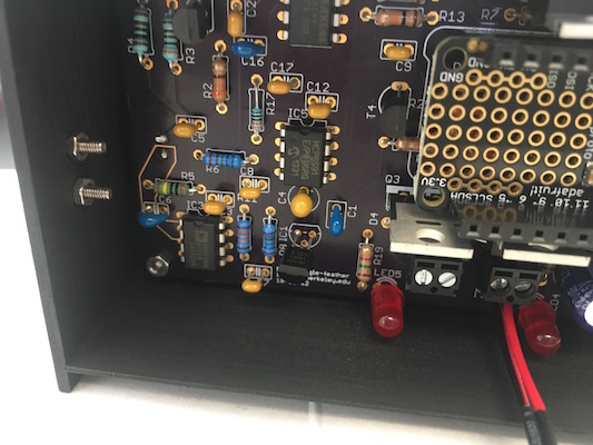
Mount the PCB in its housing
-
Insert the detector circuit board into the box, with the photodiode on the bottom passing through the square opening on the box and into the round hole in the band.

-
Align the mounting holes on the detector circuit board with the mounting holes on the box.
-
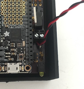
Insert M2 x 8mm screws through at least two mounting holes on the housing, passing through the circuit board. Thread M2 hex nuts onto the screws and tighten.
-
Some mounting holes are hard to access – it isn’t necessary to use all four screws.
-
-
-
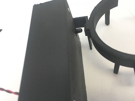
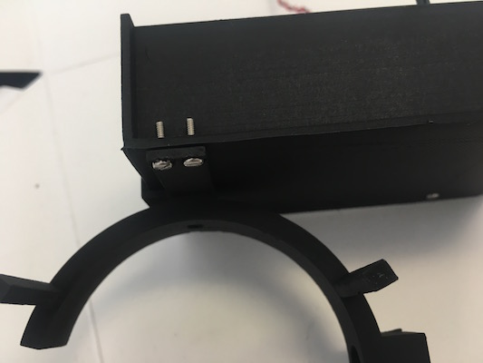
Attach the band to the PCB housing
-
Fit the band against the box.
-
The rectangular arm on the band should align with holes on the side of the box.
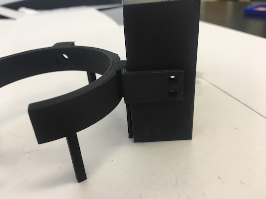
- The two flat arms extending from the band with screw holes should align with screw holes on the box.
-
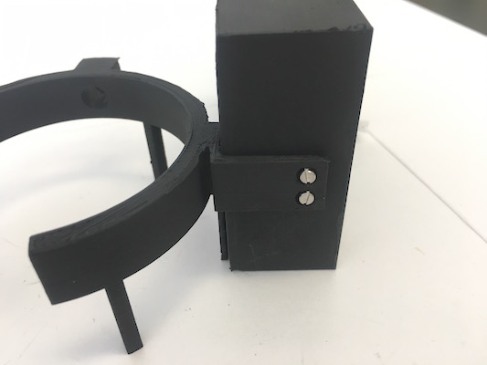
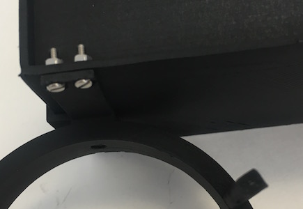
Insert M2 x 8mm screws through the holes in the band into the box.
-
Thread M2 hex nuts onto the screws and tighten.
-
The rectangular, flat leg on the band should align with holes at the bottom of the box. Insert M2 x 8mm screws through the holes in the band into the box.
-
Thread M2 hex nuts onto the screws and tighten.
-
-
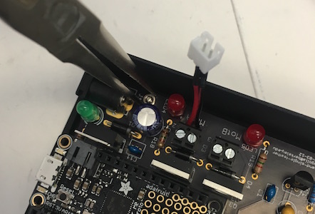
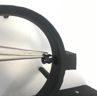
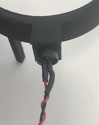
Mount the LED in the band
-
Insert the flanged LED holder into the hole on the inside of the band.
-
Press the LED holder into the hole until the flanges extend out the back.
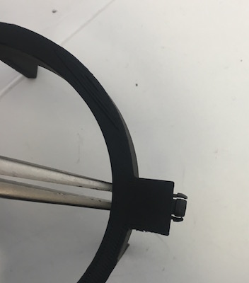
-
Thread the retaining ring over the LED onto the cables Insert the LED into the flanges.
-
Slide the ring over the flanges to clamp the LED in place.
-